Lab 5
Faraday's law
Changing magnetic fields are a source of electric fields. Faraday's law states that the emf induced in a loop is equal to the rate of CHANGE of the magnetic flux through the area enclosed by the loop. The equation below expresses Faraday's law in mathematical form.
ΔΦB/∆t (through a fixed area) = -emf
In this studio session you will use a simulation to explore consequences of Faraday's law, and another simulation to explore the inductance of circuit elements.
Open a Microsoft Word document to keep a log of your experimental procedures, results and discussions. This log will become your lab report. Address the points highlighted in blue. Answer all questions.
Activity 1
Please watch this Lenz's law demonstrations
Youtube video
https://www.youtube.com/watch?v=k2RzSs4_Ur0
Activity 1 Deliverables: (to be included in the your journal)
- Analysis: Briefly describe the three experiment performed in this video clip and explain how the demonstrate Lenz's law.
Exploration 1
(a) Use an on-line simulation from the University of Colorado PhET group to explore Faraday's law.
Link to the simulation:
https://phet.colorado.edu/en/simulations/faradays-law
What happens when a magnet moves through a coil in which a current can flow?
Your goal: Identify all variables that influence the magnitude and
direction of induced emf. Using the simulation, systematically test three
different factors (magnet speed, number of loops, magnet orientation).
(b) In a transformer, a current in one coil creates a magnetic field. When the flux of this magnetic field through the second coil changes, an induced current flows in the second coil.

- Refer to the image on the right. With a direct current (DC) flowing in the primary coil, predict what will
happen as you move the primary coil in and out of the secondary coil.
Record your predictionswith justification.
You can find out by opening the legacy app, https://phet.colorado.edu/en/simulations/legacy/faraday.
Reconcile your predictions with what the app shows you.
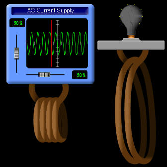
- Refer to the image on the right. With an alternating current (AC) flowing in the primary coil do you have to move the primary to light up the bulb? Why or why not? Predict and observe.
In a generator, an external force moves a magnet. The external force does work and this work is converted into electrical energy.

- Refer to the image on the right. Describe how this simple model for the generators in a hydroelectric plant works.
- Imagine you were actually turning the magnet by hand to generate a current. Neglecting friction, would you have to do work to keep the wheel turning?
Exploration 1 Deliverables: (to be included in the your journal)
- Analysis:
(a) Record your findings in a structured table and summarize a general rule for what creates the largest induced voltage.
(b) Record your predictions and compare with with your observations. Elaborate on the simple model of the generator.
Exploration 2
Use an on-line simulation from the University of Colorado PhET group to explore the inductance
of circuit elements.
Link to the simulation:
http://phet.colorado.edu/sims/html/circuit-construction-kit-ac/latest/circuit-construction-kit-ac_en.html
Click the Lab tab.
- Components are dragged from the toolbox to make circuits which can be monitored using meters and charts.
- To explore the properties of a component, tap it. You can then change many properties and also remove the component.
Construct the circuit shown below.
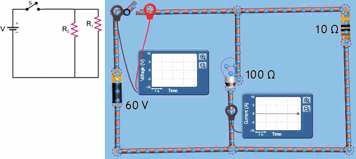
Use a 60 V battery in series with a switch, connected to a 10 Ω resistor R1 and a light bulb with resistance R2 = 100 Ω in parallel.
- Predict and Justify: Before closing the switch, draw what you think the current versus time graph for the bulb will look like. Explain the physics reasoning behind your sketch.
- Run the simulation and record the actual graph. Use a current chart to monitor the current through the bulb and a voltage chart to monitor the voltage across the switch.
- Explain/Reconcile: Did the observed behavior match your sketch? If not, what physical concept did your initial prediction overlook?
Stop the animation.
Construct another circuit as shown below.
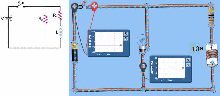
 Play the animation.
- Describe what happens to the voltage across the switch and the current
through the bulb when you close the switch.
What is the maximum current through the bulb and the maximum voltage across the switch? - Describe what happens to the voltage across the switch and the current
through the bulb when you open the switch.
What is the maximum current through the bulb and the maximum voltage across the switch? - Because the coil of a motor has a self inductance L, an emf proportional to the rate of change of the current in the coil is induced. When you flip the switch, the rate of change is very high, and the induced emf can be several times the power supply voltage. Do you observe such an induced emf?
A spark across the switch can be prevented, by connecting a diode in parallel with the inductor. A diode is an electronic component that lets current flow through it in only one direction. It has near zero resistance when "forward biased", and very high resistance when "reverse biased". When the switch is closed, the diode is reverse biased and affects the circuit minimally. When the switch is opened, the diode become forward biased and current flows through the near-zero resistance diode instead of arcing across the switch. Unfortunately the simulation does not let us put a diode into the circuit.
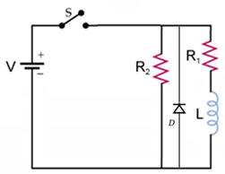
Exploration 2 Deliverables: (to be included in the your journal)
- Analysis:
- First circuit: Your prediction and justifications and how you reconciled them with your observation.
- Second circuit: What happens as you close and open the switch?
Do you observe a high induced emf (a spark)?
If you flip a switch to turn off a heavy industrial electric motor without protective circuitry, a massive spark can jump across the switch contacts. Based on your RL circuit observations, explain why this spark occurs when turning the power OFF rather than when turning it ON.
Convert your journal into a lab report.
Name:
E-mail address:
Laboratory 5 Report
- Make sure you completed the entire lab and answered all parts. Make sure you show your work and inserted and properly labeled relevant tables and plots in your journal.
- Add a summary reflection at the end of your report in a short essay format. Identify one initial assumption you had about magnetic flux or induction before this lab that turned out to be incorrect. What specific observation in the simulation corrected your thinking?
Save your Word document (your name_lab5.docx), go to Canvas, Assignments, Lab 5, and submit your document.