Studio Session 6
Electromagnetic waves
In classical physics light is assumed to be an electromagnetic wave.
Electromagnetic waves are categorized according to their frequency f or,
equivalently, according to their wavelength λ. The speed of any
electromagnetic waves in free space is the speed of light c = 3*108
m/s. Electromagnetic waves can have any wavelength λ or any frequency f
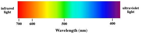
as long as λf = c. Visible light has a wavelength range from ~400 nm to
~750 nm. Violet light has a wavelength of ~400 nm, and a frequency of
~7.5*1014 Hz. Red light has a wavelength of ~700 nm, and a
frequency of ~4.3*1014 Hz.
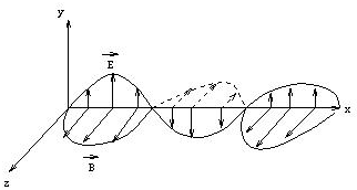
Electromagnetic (EM) waves are changing electric and magnetic
fields, carrying energy through space. EM waves require no medium, they
can travel through empty space. Let E denote the electric field
vector and B the magnetic field vector of the EM wave. For
electromagnetic waves E and B are always perpendicular to each
other, and perpendicular to the direction of propagation of the wave.
In general we pay more attention to the electric field
E, because
detectors such as the eye, photographic film, and CCDs interact with the
electric field.
Electromagnetic waves are transverse waves. Transverse waves can be
polarized. In this session you will investigate various polarization effects.
Equipment Needed:
- Optical rail with post holders
- Pasco light sensor (CI-6504A)
- Diode laser
- 3 polarizers in rotation stages
- Glass slide
- Screen
Open a Microsoft Word document to keep a live journal of
your experimental procedures and your results. Include all deliverables,
(data, graphs, analysis, outcome). Write a 'mini-reflection' immediately
after finishing each investigation, experiment or activity, while the logic is
fresh in your mind.
The inverse square law
All electromagnetic waves transport energy through space.
If a small source, for example the filament in a light bulb,
emits light, the light can be seen from every direction. Imagine a
point source emitting energy into 3D space. How does the area of a
spherical surface expand as distance increases? Sketch a graph predicting
how intensity will drop off with distance. Now test your intensity versus
distance model.
Experiment 1:
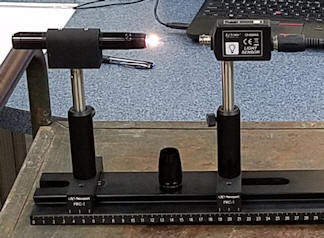
A small bright light bulb will be your point source of light,
and you will use the Pasco light sensor (CI-6504A) to monitor the intensity as a
function of the distance between the filament and the sensor. The sensor
connects to the Pasco 850 interface and outputs light intensity falling onto its active area
measured in arbitrary units. You will measure this intensity as a function
of the distance
between the sensor and the source.

- The light bulb and the sensor are mounted on the optical rail. The
sensor and the
filament of the light bulb should be at the same height and face each other.
- Plug the sensor into channel B of the Pasco 850 interface.
- Open the Capstone program.
- In the Capstone program, click the Hardware Setup
button, double click Analog Channel B and choose to add a light sensor.
- From Displays, select the Digits icon and choose to
measure Light Intensity (%).
- In the Controls panel select the Fast Monitor Mode and then
click the Monitor icon.
- The light intensity will be displayed. Initially it is proportional to
the amount of background light falling onto the sensor. To keep this
background as low as possible, turn off the room lights.
- Record the background intensity IB
in units of %.
 Turn on the light bulb by rotating the lens counterclockwise and removing it
completely.
Turn on the light bulb by rotating the lens counterclockwise and removing it
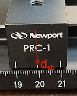
completely.- Let dsb be the location of the sensor base
on the optical rail. The initial location should be 20 cm.
The position scale on the optical rail measures the position of the sensor's
base, not the actual detector inside. How might a systematic offset between the
sensor base and the actual detector distort your data at close distances vs. far
distances?
How will you determine or account for this offset?"
- The actual distance, dact, between the filament
tip and the sensor at dsb = 20 cm is 5 cm.
- The offset distance doff = dsb
- dact is 15 cm.
- Design a sampling strategy (distance range and number of measurements) that
gives you confidence in testing your intensity vs. distance model.
- In Excel, produce a table with the following headings.
| dsb |
I |
r = dsb - doff |
I - IB |
function of r from your model |
- Move the sensor back in steps and record the measured
intensity I
for each sensor base position dsb in the table for successive base
positions. When you are done taking data, close the Capstone program.
- Produce a plot of I - IB versus the function of distance from
your model.
If you model is correct, then this plot should show a
straight line.
- Label the axes of your plot. Paste the plot into your journal.
Experiment 1 Deliverables: (to be included in the your journal)
-
Visuals:
Your plot of I - IB versus the function of distance from your
model
- Analysis:
State your intensity versus distance model.
Does your plot show a straight line? If yes, what does this mean?
If no, what could be the reason for this result?
Polarization
Activity 1:
If light propagates through a transparent material such as water or glass, it
interacts in various ways with the atoms or molecules that make up the material.
This interaction can be wavelength and polarization dependent. Due to the
interaction, light moves through a transparent material with an apparent speed v = c/n.
The index of refraction n is a property of the material. It is greater
than 1, so that v is less than c. In most transparent materials the index
of refraction depends slightly on the wavelength of the light, and in some
materials it depends on the polarization.
Linear polarization: An
ideal linear polarizer is a material that passes only light waves for which the electric
field vector is parallel to its transmission axis. If E0 is the incident
field vector and the angle between E0 and the transmission
axis is θ, then the magnitude of transmitted field
vector is E0 cosθ, and its direction is the
direction of the transmission axis. The intensity I of an electromagnetic wave
is proportional to the square of the magnitude of the electric field vector. We
therefore have
Itransmitted = I0 cos2θ.
 |
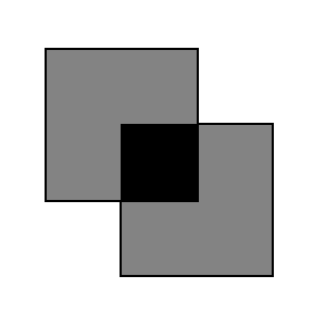 |
Polarizers with parallel
transmission axes |
Polarizers with perpendicular
transmission axes |
- Put two polarizers with their transmission axes at 90o
(crossed). No light is transmitted.
If you place a third polarizer BETWEEN the two crossed polarizers, what do
you predict will happen to the transmitted light intensity?
(Will it stay zero, decrease further, or increase?)
- Observe! Model the electric field vector direction to explain your
observation..
Put the pieces of polarizing materials back into the envelope for the next
lab session.
Experiment 2:
An incident wave has electric field amplitude E0.
When it passes through a polarizer whose transmission axis makes an angle θ with
the direction of E0, what is the component of the electric
field along the transmission axis? Since intensity is proportional
to E2 derive a mathematical model for the ratio I(θ)/I0.
This is called the Law of Malus.
In this experiment you will use a linear polarizer to produces a polarized beam and then pass this beam through a second polarizer whose
transmission axis makes an angle θ with respect to the transmission axis of the
first one. You will determine the ratio I(θ)transmitted/I0.
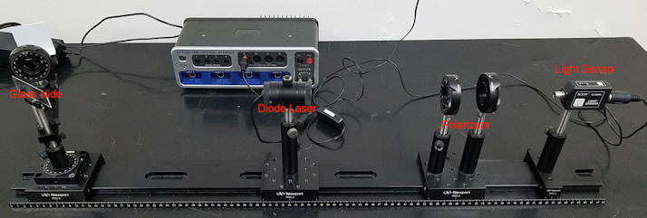
Important!
Do not move the bases on the rail. Do not remove the components from
the post holders. Only adjust the height and orientation of the
components.
- Plug the light sensor into channel A of the Pasco 850 interface.
- Open the Capstone program.
- In the Capstone program, click the Hardware Setup button, double click
Analog Channel A and choose to add a light sensor.
- From Displays, select the Digits icon and choose to
measure Light Intensity (%).
- In the Controls panel select the Fast Monitor Mode and then
click the Monitor icon.
- The light intensity will be displayed. Initially it is proportional to
the amount of background light falling onto the sensor. Make sure the
sensor's "Gain" switch is set to 1. To keep this background as low as
possible, turn off the room lights.
- Record the background intensity IB
in units of %.
- The light sensor should be tightened to the optical rail at ~ 80 cm on the rail.
- Your light source for this experiment is a diode laser.
It should be tightened to the optical rail at ~40 cm.
- Two polarizers should be mounted between the laser and the light sensor at ~
60 cm, with their transmission axes aligned vertically. The polarizer
holders should have their dial sides facing away from each other. Make
sure the polarizer disks are perpendicular to the laser beam.
- Adjust the height and angle of the laser, so that the laser beam
falls onto the sensor window. Monitor the light intensity.
(The detector is probably saturated.)
- Loosen the screw on top of the laser
and rotate the laser so that the light intensity changes to ~75% - 85%.
Then tighten the screw again and also tighten the laser post in its
post holder. For the remainder of this experiment leave the
laser and sensor undisturbed.
- After the laser light has passed through the polarizers, it is
~100% polarized along the vertical direction, since the transmission
axis of each polarizer is vertical.
In Excel create a table.
| angle (deg) |
I |
angle (rad) |
I - IB |
(I -IB/(I0- IB) |
- You will now rotate the second polarizer with respect to the first one.
Start by recording the measured intensity for zero degrees, when both
polarizers are aligned.
- Rotate the second polarizer in 10o steps. For angles between 0 and 180o in 10o steps measure
and record the intensity I in the table.
-
When you are done taking data click Stop.
- Create calculated columns
I - IB and (I -IB/(I0- IB), with the angle
in radians. I0 is the intensity you measured when the second polarizer
angle was 0.
- Create a plot of (I -IB/(I0- IB) versus angle (rad).
Label the axes.
Experiment 1 Deliverables: (to be included in the your journal)
-
Visuals: Your plot of(I -IB/(I0-
IB) versus angle (rad),
- Analysis:
Does your plot agree with what you expect from your mathematical model for
the ratio I(θ)/I0?
How can you tell?
No experiment is perfect, there are always uncertainties. Are your
uncertainties small enough so that you can tell one way or the other.
If a skeptic looked at your graph and claimed that light intensity is simply
a linear function of angle between 0o and 90o, how
would would you use your experimental results with their uncertainties to
prove them wrong?
 Polarization by reflection
When unpolarized light is incident on a boundary between
two transparent materials, for example on an air-glass boundary, then the
reflected and transmitted components are partially plane polarized. The
reflected wave is 100% linearly polarized when the incident angle is equal to
the Brewster angle θB, where tanθB
= n2/n1. The Brewster angle for reflecting off glass
is between 50o and 60o.
Experiment 3:
Challenge: You are an optical engineer designing polarized sunglasses
to minimize glare from reflective surfaces. Using the provided glass
slide, laser, and polarizers, how can you determinethe refractive index n of the
glass without measuring angles inside the glass?
Do the experiment.
You will reflect the light from a diode laser off a glass plate. You will make sure that the
incident angle is close to the Brewster angle and verify that light polarized in
the plane of incidence it will not be reflected at the Brewster angle. The
plane of incidence is a plane perpendicular to the reflecting surface that
contains the incident beam.
If the reflecting surface is horizontal, then the
plane of incidence is vertical. The reflected light at the Brewster angle is horizontally polarized and can be blocked by a polarizer with
a vertical transmission axis. If the reflecting surface is vertical, then
the plane of incidence is horizontal, and horizontally polarized light
will not be reflected at the Brewster angle. Then
the reflected light is vertically polarized at the Brewster angle and can be blocked by a polarizer
with a horizontal transmission axis. You will reflect the laser light off
a vertical glass surface (a microscope slide) and find the Brewster angle.
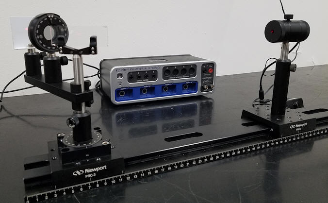
-
Set up the components on the rail as shown on the
right. Turn the diode laser so that it shines on the middle of a glass slide in a holder on a
rotation stage.
The surface of the slide is vertical.
The angle of incidence can be changed by rotating the stage. Fix the rotation stage at 0.
Rotate the post in the holder until the light reflecting off the slide reflects
back onto itself in the horizontal direction, and then tighten the
post in the post holder. (Block the transmitted beam to
prevent it from shining into another person's face.)
- Rotate the polarizer in front of the screen by 90o,
so that its transmission axis is horizontal. It now blocks
vertically polarized light.
-
Using the rotation stage, rotate the slide approximately 55o.
Follow the reflected beam with the screen, by rotating the arm it is
mounted on. Find the angle at which the
reflected intensity is lowest.
- Iterate by adjusting the transmission axis of the polarizer and the
incident angle until the reflected intensity is practically zero.
Record the angle through which you have
rotated the rotation stage. This is the Brewster angle for the
glass slide in air.
- Use this measured value to find the
index of refraction of the microscope slide.
We have tanθB
= nglass/nair = nglass, since nair = 1.
- Keep the rotation stage fixed at the Brewster angle and rotate
the polarizer. You should see a reflected beam. At the
Brewster angle the reflected beam should be 100% vertically
polarized.
Convert your journal into a lab report.
Name:
E-mail address:
Laboratory 6 Report
- Make sure you completed the entire lab and answered all parts. Make
sure you show your work and inserted and properly labeled relevant tables
and plots in your journal.
- Add a summary reflection at the end of your report in a short essay format.
Save your Word document (your name_lab6.docx), go to Canvas, Assignments, Lab
6, and submit your document.