
In this lab students will build a paraxial four-lens ray-optics cloak. The theory and experimental realization of such a cloak are described in a paper by Choi and Howell (University of Rochester). You can also find this paper under Modules on Canvas.
Equipment:
Open a Microsoft Word document to keep a live journal of your experimental procedures and your results. Include all deliverables, (data, graphs, analysis, outcome). Write a 'mini-reflection' immediately after finishing each investigation, experiment or activity, while the logic is fresh in your mind.
Summary of the key points of the paper concerning a four-lens ray-optics cloak:
A paraxial cloak is an optical system that makes light behave as if the system were not there. In the small-angle (paraxial) limit, this means that if rays enter the system at some height and angle, they exit with the same angle. Their positions shift exactly as they would if they had simply traveled through empty space of the same length. If this happens, anything placed inside the "empty" region of the system becomes hidden from view.
Why four lenses?
Using ABCD matrices, you can show that 1-lens and 2-lens systems cannot satisfy the cloak conditions. A 3-lens systems can get close, but never exact. A 4-lens system is the simplest exact solution that still leaves a real, non-zero cloaking region. The four-lens cloak is the first system that can mathematically behave like a "perfect" paraxial cloak.

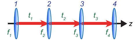
The system is symmetric.
Lens 1 and Lens 4 have the same focal length, f1 = f4.
Lens 2 and Lens 3 have the same focal length, f2 = f3.
The outer spacings are the same, t1= t3.
This symmetry ensures that whatever the first half of the system does to the
rays, the second half undoes.
To behave like a perfect cloak, the system must satisfy
t1 = f1 + f2,
t2 = 2f2(f1 + f2)/(f1 – f2),
total length L = 2f1(f1 + f2)/(f1 – f2).
These relations guarantee that the ABCD matrix of the whole system matches that
of free-space propagation.
Because the system is afocal and symmetric, rays bend inward and then outward
again, leaving a central cylindrical region where no rays pass.
Anything placed inside this region is hidden from the observer - at least for
small angles.
Experimental Realization
To build a real cloak, the authors used achromatic doublets instead of simple thin lenses. This reduces chromatic and spherical aberrations, so the image behind the cloak looks sharp.
Components
Four lenses with the focal lengths chosen to satisfy the cloak equations.
Assembly
The lenses mounted on an optical rail, the spacings are set to the corrected values of t1, t2, and t3,
where the lens thicknesses are considered when setting the actual separation.
The field of view is about ±1.5o.
Imaging Setup
A background grid placed ~1.9 m behind the rear lens. A camera placed ~3.1 m in front of the front lens.
The camera zoomed in (21×) to make distortions easy to see. A ruler placed inside the cloaking region (behind lens 2).

What Students Should Notice
The grid lines seen through the cloak match the background grid in size and
position. The middle of the ruler disappears from view. Cloaking works for a continuous range of small viewing angles.
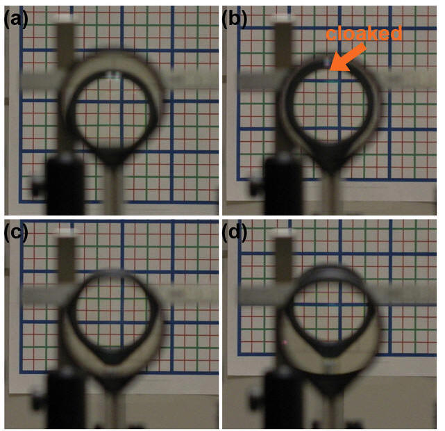
Video: The Rochester Cloak
Video:
A
different type of cloak (just for fun)
Procedure:
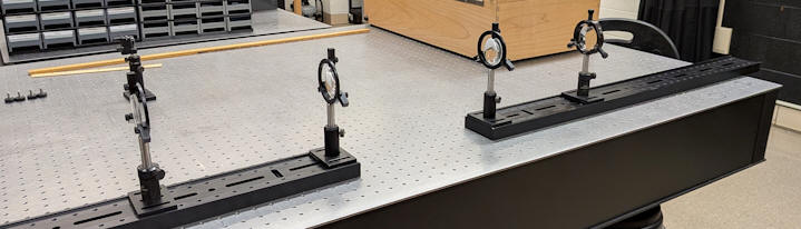
In this lab, you just will use thin lenses. You will use two f1 = 200 mm lenses (KPX199 or KBX166) and two f2 = 75.6 mm lenses. You will use the laser as an alignment tool.
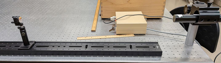
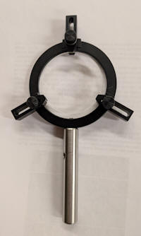 Center one f1 and one f2
lens in a lens holders, assemble post holders, posts, and lenses and
center each lens individually on the rail.
Center one f1 and one f2
lens in a lens holders, assemble post holders, posts, and lenses and
center each lens individually on the rail. 

Deliverables:
(to be included in the your journal)
Laboratory 3 report: