
A fiber optic data link has three basic functions. It must convert an electrical input signal to an optical signal, send the optical signal over an optical fiber, and then convert the optical signal back to an electrical signal.
The transmitter converts the electrical input signal to an optical signal. Its drive circuit varies the current flow through the light source, which in turn varies the irradiance of the source. The process of varying the irradiance as a function of time is called modulation.
Fiber-optic telecommunication systems use pulse-code modulation. Information is transmitted as a series of pulses. The digital pulse-code-modulated signal is coupled into a fiber. The fiber end is positioned by a connector to maximize the input power. Semi-conductor lasers are well-suited for use in a fiber-optic communication system. Their size and shape allows for efficient coupling of light into the small-diameter core of an optical fiber. Modern AlxGa1–xAs lasers operate continuously at mW power levels. Their output can be modulated easily at frequencies into the GHz range by modulating the output of an electric power supply.
Many existing systems use AlxGA1–xAs source lasers or LEDs operating near 0.85 μm. Such systems are termed "short-wavelength" systems. "Long-wavelength" systems use InGaAsP and InP sources operating near 1.3 μm and 1.55 μm. These sources are less well developed than the AlxGA1–xAs sources, but power loss in an optical fiber at the longer wavelengths is lower than at 0.85 μm and the dispersion is near zero.
The fiber carries the light toward the receiver, where the light is detected and the digital signal is recovered. Since absorption, scattering and dispersion in the fiber degrade the signal, optical amplifiers are needed to regenerate the signal. Current technology usually requires repeaters every few kilometers.
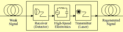
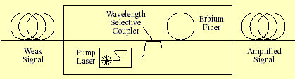
A modern repeater consist of an optical amplifier, a fiber-laser without a laser cavity. A fiber laser consist of a properly doped fiber which can be pumped with an external light sources to produce stimulated emission. A typical fiber amplifier works in the 1550 nm band. It consists of a length of fiber doped with Erbium, which is pumped with a 980 nm laser. This pump laser supplies the energy for the amplifier, while the incoming signal stimulates emission as it passes through the doped fiber. The stimulated emission stimulates more emission. The number photons in the doped fiber increases exponentially. Gains of greater than 40 dB are possible.
Link: Fiber Amplifiers
The receiver converts the optical signal exiting the fiber back into an electrical signal. The receiver consists of an optical detector and a signal-conditioning circuit. The optical detector can be either a semiconductor PIN diode, whose electrical conductivity is a function of the intensity and wavelength of the light signal, or an avalanche photodiode detector.
For AlxGA1–xAs sources, silicon photodiodes are suitable detectors. Silicon photodiodes offer excellent high-frequency response at wavelengths up to 1.1 μm. They have peak spectral response near 0.9 μm, close to the wavelength of AlxGA1–xAs lasers. At longer wavelengths, in particular at 1.3 μm, germanium or InGaAsSb photodiodes must be used.
A fiber optic data link also includes passive components other than an optical fiber. Passive components used to make fiber connections affect the performance of the data link. Fiber optic components used to make the optical connections include optical splices, connectors, and couplers.
The maximum speed at which a signal may be transmitted through an optical fiber is limited by the rate at which electronics can modulate the source and by dispersion in the fiber. Currently the electronics can modulate the source at a maximum frequency of ~10 GHz. This limits the transfer rate in a single mode fiber. To transmit information at a rate of greater than 10 Gbit/s wavelength division multiplexing (WDM) is used. Multiple signals each at a different wavelength are transmitted through the same optical fiber.

The multiplexer and demultiplexer typically consist of some type of optical diffraction grating. The total number of channels, or wavelengths ranges from 2 to over 100. The separation between wavelengths, Δλ = (λ2/c)Δf, ranges from 0.4 to 3.2 nm, with the nominal wavelength about 1550 nm.