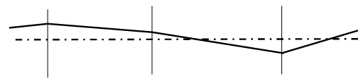
A light ray propagates through an optical system, close to the optical axis (small angle approximation) from left to right. It encounters a series of refracting and reflecting surfaces and between any two surfaces a medium with some index of refraction n. At the surfaces, the light ray can change direction, and between the surfaces it propagates along a straight line path.
We can trace a light ray through such an optical system
from some initial position along the optical axis through some final position
along the optical axis. At any point along the optical axis the ray is
completely defined by a column vector
 ,
,
where θ is the angle it makes with the optical axis, x is its perpendicular
distance away from the optical, axis and n is the index of refraction of the
medium at that point.
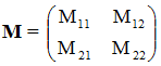
To trace the ray through the system from a point A to a point B along the optical axis we have to multiply it by a 2 x 2 matrix
 ,
,
representing the system between points A an B.
The system matrix for an optical system is obtained by multiplying together the appropriate matrices for translation, refraction by a surface, refraction by a thin lens or reflection in the correct order.
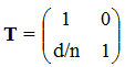
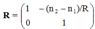
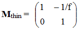
Consider a system of two thin lenses of focal length f1 and
f2 respectively, separated by a distance d in air.
Find the system
matrix connecting the left side of lens 1 to the right side of lens 2.

In the paraxial approximation, once we have found the system matrix M of an optical system, from some first surface to some last surface, we know everything about the optical properties of this system.
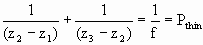
For a thin lens the distance between the refracting surfaces goes to zero and all the refraction is considered to occur at a single plane at the center of the lens. For a thin lens the relationship between the object and the image position is very simple. If n1 = n2 = 1, then f = f’ = 1/Pthin and
 .
.
For an optical system such as a thick lens or a compound lens, the refracting surfaces are not necessarily close together. The initial and final refracting surfaces intersect the optical axis at V and V’. The transformation matrix from V to V’ has the general form
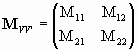 ,
det(M) = 1.
,
det(M) = 1.
We can show that if we measure the object and image distance S1 and S2 from some reference planes H and H' instead of from the vertices V and V', then any optical system can be treated like a thin lens.
If n1 = n2 = 1, the equation relating the object and image
distance then is
1/S1 +
1/S2 = 1/feff.
S1 and S2 are the image and the object distance, respectively, from the principal planes. The principal plane are reference planes, a distance D1 and D2 away from the actual left and right boundary surfaces of the optical system.
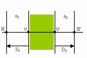
We calculate feff, D1 and D2 using D1 = (1 - M11)/M12, D2 = (1 - M22)/M12, and 1/feff = Psys = -M12.
For arbitrary n1 and n2 we have

In the paraxial approximation any optical system behaves like a single lens when referred to the overall system principle planes.
Link: A spreadsheet finding the principal planes and focal points of a single, thick lens
AI Study Tip
Example prompt: (Check your manual matrix multiplication.)
I am designing a two-lens system. Lens 1 (f1 = 10 cm) is
separated from Lens 2 (f2 = 5 cm) by a distance of 15 cmin air.
Act as an expert in matrix optics and help me calculate the total system matrix
M.
Use the ray transfer equation  .
.
Remind me of the correct multiplication order (right-to-left) and why it's
necessary. Once we have the system matrix M, help me find the effective
focal length of this combination. Does this system act as a converging or
diverging unit?
Example prompt:
I have the system matrix for a thick lens (two spherical surfaces of radius R1
and R2 separated by thickness d).
Help me derive the positions of the two principal planes (H1 and H2)
relative to the lens surfaces using the matrix elements.
Why can we treat a complex thick lens as a 'thin lens' if we measure distances
from these principal planes instead of the physical center?
Create a table for me showing how the system matrix changes if the lens is 'plano-convex'
versus 'bi-convex' while keeping the total power the same.
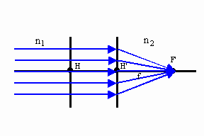 If the object distance S1 goes to infinity, so that the incident
rays are parallel, then the image distance S2 becomes the image focal
length f’ to the image focal point F’.
If the object distance S1 goes to infinity, so that the incident
rays are parallel, then the image distance S2 becomes the image focal
length f’ to the image focal point F’.
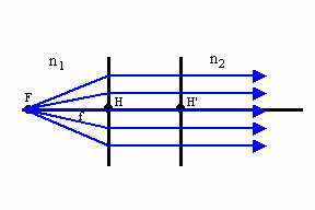 If the image distance S1 is at infinity, then the object distance
S1 identifies the object focal length f to the object focal point F.
If the image distance S1 is at infinity, then the object distance
S1 identifies the object focal length f to the object focal point F.

If n1 = n2, then we obtain 1/S1 + 1/S2 = 1/f, the elementary form of the thin lens equation.
If the principal planes and the focal points are known, three rays can easily be drawn to locate the position and determine the size of the image.
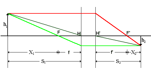
Rays that leave the object parallel to the optical axis continue parallel to the H' plane and then pass through (or appear to pass through) the image focal point. Rays that leave the object and pass through (or appear to pass through) the object focal point proceed to the H plane and then continue parallel to the optical axis. Rays that leave the object and pass through H move along the optical axis to H' and then proceed moving parallel to their original direction.
Inspecting the figure above, we find (using similar triangles:
h2/X2 = h1/f',
h1/X1 = h2/f
Combining these two equations we obtain
X1X2 = ff'
This is called Newton's form of the lens equation.