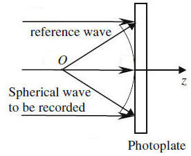
In the late 1948 Dennis Gabor developed the concept of holography. Gabor filtered light and passed it through a pinhole to produce a coherent source. The source illuminated a small, semi-transparent object O that allowed most of the light to fall undisturbed on a photographic plate, where it interfered with light scattered or diffracted by the object. The resulting interference pattern contains enough information for a complete reconstruction of the object.
To find the intensity at the photographic plate we may write the field arriving at
the plate as
E = Ei + EO,
where Ei is the field due to the coherent background called the
reference beam, and EO is the field
scattered by the object.
Both amplitude and phase of the scattered field EO at the plate vary greatly with position.
We
therefore write
EO = AOexp(iφO),
where AO and φO are functions of position. We
write a similar expression for Ei,
Ei = Aiexp(iφi).
If the reference wave is incident perpendicular to the photographic plate, as
shown in the figure above, then Ai and φi are constant.
The field falling on the plate is
E = Aiexp(iφi)+ AOexp(iφO),
and the intensity is
I ∝ |E|2 = Ai2 + AO2
+ AiAOexp(i(φO - φi)) + AiAOexp(-i(φO
- φi)).
Photographic plates used for holography are characterized by a curve of amplitude transmittance Ta versus exposure ℇ that is nearly linear over a short region, with slope β. In that region we may write Ta = To - βℇ.

Given an exposure time t, the amplitude transmittance of the developed
plate is
Ta = To - βt[Ai2 + AO2
+ AiAOexp(i(φO - φi)) + AiAOexp(-i(φO
- φi))].
The scattered background term AO2 is small compared to
the coherent background term Ai2 and we can safely drop
the AO2 term.
If we remove the object O and illuminate the developed photographic plate
with the original reference beam Ei, then the transmitted field Et just beyond the
plate is
Et = Aiexp(iφi)Ta
= Aiexp(iφi)T0
- Aiexp(iφi)βt[Ai2
+ AiAOexp(i(φO - φi)) + AiAOexp(-i(φO
- φi))].
Et = E1 + E2 + E3, where
E1 = Aiexp(iφi)[T0
- βtAi2],
E2 = βtAi2[AOexp(iφO)],
E3 = βtAi2[AOexp(-i(φO
- 2φi)].
E1 is just a reduced amplitude version of the reference beam. E2 is the reconstructed wave. Except for a reduced amplitude, it is identical to the scattered wave from the object. An observer looking through the plate would see a virtual image of the object located in the original position of the object.
E3 is the conjugate wave. It is similar to the object wave but has the opposite curvature. This term corresponds to a second reconstruction, located on the opposite side of the plate. This conjugate reconstruction forms a real image and is always present. For an observer focusing on the primary reconstruction, the conjugate reconstruction is out of focus.

The presence of the conjugate reconstruction degrades the primary reconstruction. When lasers providing intense coherent light became available, it became possible to split one coherent beam and separate the reference beam and the beam scattered from the object. The primary and conjugate reconstructions are then partially separated so that they do not interfere with one another.

AI Study Tip:
Example prompts:
Mathematically, a hologram is a recorded interference pattern between an object wave E0 and a reference wave Ei. When we illuminate the developed hologram with the reference wave again, the transmitted wave is proportional to Ei*|E0 + Ei|2. Can you expand this expression and identify which term represents the 'reconstructed object wave' and which term represents the 'conjugate image'?
In early in-line holography, the reconstructed image was often obscured by the direct beam and a twin image. Explain how the off-axis technique solved this problem using spatial frequency separation.
If we inspect a hologram plate visually, we see that the spacing of the interference maxima varies with position across the plate. The difference in optical path length between the object and reference beam being equal to mλ determines the position and the spacing of the maxima. To find this difference we use a Fresnel construction for each object point, just as we do for a zone plate.
A hologram resembles a superposition of zone plates. Each zone plate is made by the interference of two beams and ideally has a sinusoidal amplitude transmittance, so there is only one positive and one negative focal length. For a collimated reference beam these focal lengths are equal to the perpendicular distance of the object from the plate. When the reference beam originates at a point at a finite distance from the plate, the focal lengths f and f' are, in general, not equal but must be determined using the lens equation.
The zone-plate interpretation of the hologram shows us why two reconstructions exist, and also lets us find their positions.
An amplitude hologram is a hologram normally recorded on film. The developed film looks dark. A large percentage of the reference beam is absorbed and does not contribute to the reconstruction. The diffraction efficiency of a hologram is the percentage of the reference beam that is diffracted into the primary reconstruction. The diffraction efficiency of an amplitude hologram depends on the contrast of the recorded fringes, which is quite low because of the T0 term in the transmittance,
Bleaching is a chemical process that convert the silver image on the film into a silver salt that is transparent. The salt has a slightly different refractive index from the gelatin. This makes it possible to convert the amplitude hologram to a nearly transparent phase hologram. The phase hologram has nearly constant transmittance, but provides a reconstruction, just as an amplitude hologram does.
[If
Ta = To - βt[Ai2 + AO2
+ AiAOexp(i(φO - φi)) + AiAOexp(-i(φO
- φi))],
then for phase hologram we have
Et = Aiexp(iφi)exp(iεTa) ≈ Aiexp(iφi)(1
- iεTa).
We can again write Et = E1 + E2 + E3,
but now E1 does not have a greatly reduced amplitude and the contrast
of the recorded fringes is quite high.]
AI Study Tip:
Example prompts: