Laboratory 6
Objective:
In this lab students will study the diffraction patterns of slits and circular apertures. They will study the patterns in the Fraunhofer regime.
Equipment:
- Laser Assembly
- Beam Steering Assemblies
- Adjustable aperture
- Target Assemblies
- Targets
- Meter Stick
- Index Cards
Open a Microsoft Word document to keep a live journal of your experimental procedures and your results. Include all deliverables, (data, graphs, analysis, outcome). Write a 'mini-reflection' immediately after finishing each investigation, experiment or activity, while the logic is fresh in your mind.
Procedure:
Set up the laser assembly and beam steering assembly and target pinhole as shown in the picture.
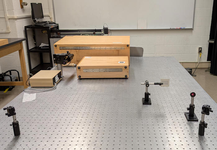
 Make sure the "square" is large enough so that the
naturally expanding beam easily covers pinholes of different sizes. Make
sure the horizontal beam is high enough above the optical table so you can observe the whole diffraction pattern on the whiteboard. Use 3 inch post
holders.
Make sure the "square" is large enough so that the
naturally expanding beam easily covers pinholes of different sizes. Make
sure the horizontal beam is high enough above the optical table so you can observe the whole diffraction pattern on the whiteboard. Use 3 inch post
holders.
Part 1:
Fraunhofer diffraction of a circular mask
Start with the adjustable aperture and produce the smallest possible pinhole.
Observe and diffraction pattern on the whiteboard and make measurements.
Use the results of your measurements to determine the size of the pinhole.
Refer to Module 6,
Diffraction.
Increase the size of the pinhole twice by a small amount and repeat.
Construct a table as shown below.
| pinhole 1 | pinhole 2 | pinhole 3 | |
|---|---|---|---|
| pinhole-target distance (L) | |||
| diameter of first dark band (a) | |||
| measured sinθ ~ θ ~ a/(2L) | |||
| diameter of pinhole (D) | |||
| D2/Lλ |
Evaluate if your measurements were made in the Fraunhofer
regime. Your measurements were made in the Fraunhofer regime if D2
<< Lλ.
Link:
When is the Fraunhofer
approximation valid?
Part 1 Deliverables: (to be included in the your journal)
- Visuals: A picture of your setup.
- Table: Filled out table.
- Analysis: Discuss your results. Does the diffraction patter look as expected? Are your measurements made in the Fraunhofer regime? Do you have suggestions for making better measurements?
Part 2:
Single slit diffraction and double slit interference
Replace the adjustable aperture with a target assemblies. Determine the width of a single slit, the slit spacing for a double slit, and the distance d between adjacent wires and the width w of the gap between the wires of 2-dimensional wire mesh.
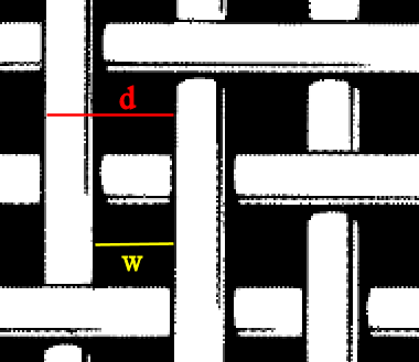
Construct tables as shown below.
| Single Slit | |
|---|---|
| slit-target distance (L) | |
| distance between dark bands (a) | |
| measured sinθ ~ θ ~ a/L | |
| slit width (w) |
| slit-target distance (L) | Double Slit |
|---|---|
| distance between maxima (a) | |
| measured sinθ ~ θ ~ a/L | |
| slit separation (d) |
Wire mesh:
- Observe the 2-dimensional diffraction/interference pattern on the whiteboard.
- Measure the distance between the center of the pattern and the mth interference maximum and the mesh-screen distance to find sinθ.
- Calculate the distance d between adjacent wires from d sinθ = mλ.
- Measure the distance from the center of the pattern and the first diffraction minimum (where an interference maximum is missing) and find sinθ'.
- Calculate the width w of the gap between the wires from w sinθ' = λ
| slit-target distance (L) | wire mesh |
|---|---|
| distance between the center of the pattern and the mth interference maximum (a) | |
| measured tanθ = a/L | |
| groove separation (d) | |
| distance from the center of the pattern and the first diffraction minimum | |
| width w of the gap between the wires |
- Observe the 2-dimensional diffraction/interference pattern on the screen.
- Measure the distance between the center of the pattern and the mth interference maximum and the mesh-screen distance to find sinθ.
- Calculate the distance d between adjacent wires from d sinθ = mλ.
- Measure the distance from the center of the pattern and the first diffraction minimum (where an interference maximum is missing) and find sinθ'.
- Calculate the width w of the gap between the wires from w sinθ' = λ
Part 2 Deliverables: (to be included in the your journal)
-
Visuals: Pictures of the diffraction pattern of the wire mesh.
Tables: Filled out tables. - Analysis: Discuss your results. Do the measured patterns look as expected? If not, why not? Did you have any problems making the measurements? Do you have suggestions for making better measurements?
Optional observation:
Fresnel Diffraction of Circular Mask
Use the Fresnel target. Look atthe diffraction pattern on a target screen. Note that the center of the image has several bright and dark rings. This is Fresnel diffraction. Depending on the target-screen dstance, the center of the pattern may be bright or dark. Although the Fresnel target has a central absorbing circle, note there is still light at the center of the pattern. The bright spot at the center is sometimes called the Poisson spot orthe spot of Arago.