The single slit
If the wavelengths of the light become comparable to the dimensions of the
equipment, then we study optical phenomena using the classical theory of
radiation, or wave optics. Wave optics contains all of ray optics, but the
mathematical treatment is much more involved.
Diffraction and interference are phenomena observed with all waves.
Diffraction can only be observed with waves traveling in two or three
dimensions.
 Diffraction is the tendency of a wave emitted from a finite source or
passing through a finite aperture to spread out as it propagates. Diffraction results from the interference of an infinite number of waves
emitted by a continuous distribution of source points in two or three dimensions.
Huygens' principle
lets us treat wave propagation by considering every point on a wave front to be a secondary source of
spherical wavelets. These wavelets propagate outward with the characteristic
speed of the wave. The wavelets emitted by all points on the wave front interfere
with each other to produce the traveling wave. Huygens' principle also holds
for electromagnetic waves. When studying the propagation of light, we can
replace any wave front by a collection of sources distributed uniformly over the
wave front, radiating in phase.
Diffraction is the tendency of a wave emitted from a finite source or
passing through a finite aperture to spread out as it propagates. Diffraction results from the interference of an infinite number of waves
emitted by a continuous distribution of source points in two or three dimensions.
Huygens' principle
lets us treat wave propagation by considering every point on a wave front to be a secondary source of
spherical wavelets. These wavelets propagate outward with the characteristic
speed of the wave. The wavelets emitted by all points on the wave front interfere
with each other to produce the traveling wave. Huygens' principle also holds
for electromagnetic waves. When studying the propagation of light, we can
replace any wave front by a collection of sources distributed uniformly over the
wave front, radiating in phase.
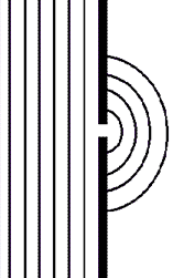 When light passes through a small opening, comparable in size to the
wavelength λ of the light, in an otherwise opaque obstacle, the wave front on
the other side of the opening resembles the wave front shown on the right.
When light passes through a small opening, comparable in size to the
wavelength λ of the light, in an otherwise opaque obstacle, the wave front on
the other side of the opening resembles the wave front shown on the right.
The light spreads around the edges of the obstacle. This is the phenomenon of
diffraction.
When light passes through a single slit whose width w is on the order of the wavelength of the light, then we can observe a single slit diffraction pattern on a
screen that is a distance L >> w away from the slit. The intensity is a function of angle. Huygens' principle tells us that each part of the slit can be thought of as an
emitter of waves. All these waves interfere to produce the diffraction pattern. Where crest meets crest we have constructive interference and
where crest meets trough we have destructive interference.
Maxwell's equations define classical electromagnetism, and therefore
classical wave optics. Many types of active optical phenomena and devices
are excluded. A laser is an example of an active optical device. But
classical optics is used to design the resonator cavity to confine the optical
fields within the active laser medium.
Maxwell’s equations lead to a vector formulation of diffraction i.e. to a
mathematical formulation of Huygens' graphical construction. In the old days of
optics, scalar equations similar to the vector equations derived from Maxwell’s
equations were derived in various ad hoc ways. An example is the
Fresnel diffraction theory. It
derives the Fresnel diffraction integral, which in principle, can be evaluated
for any source distribution in front of any aperture to predict the intensity
distribution of the diffracted light behind the aperture at any distance.
However, the integral can most often only evaluated numerically. This must
be done when the sources are located near the apertures and/or the diffraction
pattern close to the apertures is to be calculated. In this regime the
wave fronts are curved at the apertures.
>
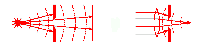
Very far from a point source the wave fronts are essentially plane
waves. This is called the Fraunhofer regime, and the diffraction pattern is called Fraunhofer
diffraction. The Fraunhofer approximation of the Fresnel diffraction
theory is only valid when the source, aperture, and detector are all very far apart or
when lenses are used to convert spherical waves into plane waves. Being
very far apart means that the distances between source, aperture, and detector
must be much greater than the width of the aperture.
>

Fraunhofer approximation
Assume light from a distant source passes through a narrow slit
as shown on the figure below. Assume the incident wave can
be treated as a plane wave E(r,t) = k Ecos(kx -
ωt + φ). The polarization of this wave
perpendicular to the plane of the figure. Let the slit be
very long. Let us concentrate on the region near the middle of the slit
and neglect variations of the transmitted wave perpendicular to the
plane of the figure. (We are reducing the problem from a 3D to a
2D problem.) What do we observe on a distant screen?

According to the Huygens-Fresnel principle, the total field at a point y
= d*tanθ on a screen a large distance d from the slit is the
superposition of radiation fields from an infinite number of point sources in the aperture region. Each
section on the wave front between s and s + ds inside the aperture
(-a/2 ≤ s ≤ a/2) is the source of a spherical wave. A large distance r from
the point source between s and s + ds the radiation field is due to the sources is
dE = (Asds/r)cos(kr - ωt).
Here Asds/r the field at a distance r from the point
source of infinitesimally small width ds.
If r0 = d is the distance from the point s = 0 on the optical axis to a point y on
the screen, then the contribution dE to the total amplitude on the
screen from the point at s = 0 is
dE(y = d*tanθ) = (Asds/r0)cos(kr0
- ωt).
For
off-axis points for which s ≠ 0, the distance to the screen is longer or shorter than
r0 by an amount Δ.
The contribution dE(y) to the total amplitude on the screen from an off-axis point (s ≠ 0) is
dE(y) = (Asds/(r0 + Δ(s))) cos(k(r0 + Δ(s)) - ωt).
To find the total amplitude E(y) we have to add up the contributions from all
points on the aperture. Because there are an infinite number of points,
the sum becomes an integral.
E(y) = ∫-a/2+a/2(A/(r0 + Δ(s)))cos(k(r0 +
Δ(s)) - ωt)ds.
We define sinθ = Δ/s. Since r0 >> Δ, we approximate 1/(r0
+ Δ)
with 1/r0. However we cannot drop the Δ inside the cosine
function, since kΔ(s) is not necessarily much smaller than 2π. We then have
E(y) = (As/r0)∫-a/2+a/2cos[(ksinθ)s
+ (kr0 - ωt)]ds.
Using ∫cos(ax + b)dx = (1/a)sin(ax + b) the integration yields
E(y) = (Asa/r0)cos(kr0
- ωt)(sin(ka(sinθ)/2)/(ka(sinθ)/2).
or, inserting k = 2π/λ,
E(y) = (Asa/r0)cos(kr0
- ωt)(sin(πa(sinθ)/λ)/(πa(sinθ)/λ).
The function sin(x)/x = sinc(x) is called the sinc function.
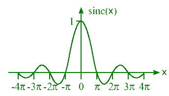
The intensity is proportional to the square of the field, I(y)
 E2(y). Since the square of a cosine function
averages to ˝, the time-averaged intensity is given by
E2(y). Since the square of a cosine function
averages to ˝, the time-averaged intensity is given by
<I(y)> = <I0>sin2(πa(sinθ)/λ)/(πa(sinθ)/λ)2,
where <I0> is the average intensity at the center.
The time-averaged intensity has a peak in the center with smaller fringes on
the sides. For small angles we may approximate sinθ ~ θ. Then the first zeros on the sides
of the central peak occur when πasinθ/λ ~ πaθ/λ = π,
or θ = λ/a.
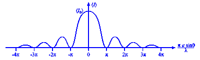
On the screen we see a pattern similar to that shown in the figure
below.

Diffraction of light through a rectangular aperture is
a rather straightforward extension of 1-dimensional diffraction from a
slit, as shown in the diagrams below.


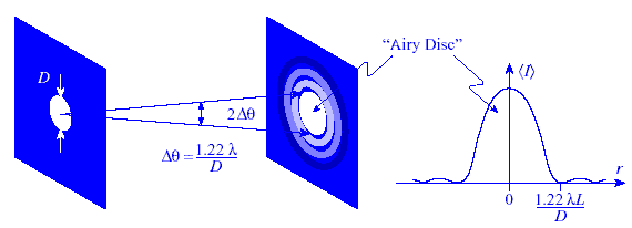
 A circular aperture is qualitatively similar, but an
accurate quantitative treatment of the pattern requires more complicated
mathematics. The intensity pattern is called the "Airy Disk".
The main features are shown in the diagram below. The
first minimum occurs at an angle θ = 1.22 λ/D, where D is
the diameter of the aperture. On a screen a distance L >> D from the aperture
the minimum is seen at a radial distance r' = 1.22 λL/D from the center of the pattern
A circular aperture is qualitatively similar, but an
accurate quantitative treatment of the pattern requires more complicated
mathematics. The intensity pattern is called the "Airy Disk".
The main features are shown in the diagram below. The
first minimum occurs at an angle θ = 1.22 λ/D, where D is
the diameter of the aperture. On a screen a distance L >> D from the aperture
the minimum is seen at a radial distance r' = 1.22 λL/D from the center of the pattern
Producing a laser beam is an attempt to confine the light in the directions
transverse to the direction of propagation. The light will spread out in the
same way it does after passing through an aperture.
Assume that at z = 0 the diameter of a laser beam is restricted to a(0). The angle through which the light spreads is approximately
θ ≈ λ/a(0). (For back-of-the-envelope calculations we
often ignore the factor of 1.22.) Because the laser beam diameter is
typically much larger the wavelength of light, or a(0) >> λ, θ is quite small.
At a large distance z the diameter of the beam will have increased to a(z) ≈ z*2θ. Consider a HeNe laser, for which λ = 633 nm with a beam waist of ~ 0.6 mm. Then
θ
~ 10-3 rad = 1 millirad. The beam must propagate ~ 3 m before
the diameter increases by a factor of 10.

 In geometrical optics we assume that an ideal, aberration-free lens focuses
parallel rays to a single point one focal length away from the lens. But the
lens itself acts like an aperture with diameter D for the incident light. The
light passing through the lens therefore spread out. This yields a blurred spot
at the focal point. Light near the focal point exhibits an Airy Disc pattern. The size of the Airy Disc is determined by the focal length f and diameter D of
the lens. The radius r of the Airy Disc at the focal point of a lens is given by
r = 1.22 λf/D.
In geometrical optics we assume that an ideal, aberration-free lens focuses
parallel rays to a single point one focal length away from the lens. But the
lens itself acts like an aperture with diameter D for the incident light. The
light passing through the lens therefore spread out. This yields a blurred spot
at the focal point. Light near the focal point exhibits an Airy Disc pattern. The size of the Airy Disc is determined by the focal length f and diameter D of
the lens. The radius r of the Airy Disc at the focal point of a lens is given by
r = 1.22 λf/D.
If all ray aberrations in an optical system can be eliminated, such that all
of the rays leaving a given object point land inside of the Airy Disc associated
with the corresponding image point, then we have a diffraction-limited optical
system. This is the absolute best we can do for an optical system that has
lenses with finite diameters.
The resolving power of an
optical instrument is its ability to separate the images of two objects, which
are close together. Some binary stars in the sky look like one single star when
viewed with the naked eye, but the images of the two stars are clearly resolved
when viewed with a telescope.
If you look at a far-away object, then the image of the object will form a
diffraction pattern on your retina. For two far-away objects, separated by a
small angle θ, the diffraction patterns will overlap.
You are able to resolve the two objects as long as the central maxima of the two
diffraction patterns do not overlap. The two images are just resolved when one
central maximum falls onto the first minimum of the other diffraction pattern. This is known as the
Rayleigh criterion. If
the two central maxima overlap the two objects look like one.

The width of the central maximum in a diffraction pattern depends on the size
of the aperture, (i.e. the size of the slit). The aperture of your eye is your
pupil. A telescope has a much larger aperture, and therefore has a greater
resolving power. The minimum angular separation of two objects which can just be
resolved is given by θmin = 1.22 λ/D,
where D is the diameter of the aperture. The factor of 1.22 applies to circular
apertures like the pupil of your eye or the apertures in telescopes and cameras.

When light passes through an aperture with diameter D, then diffraction
limits the resolution to θ = 1.22λ/D. If the angular separation of two
sources is less than θ, they cannot be resolved. The closer you are to two objects, the greater is the angular separation
between them. Up close, two objects are easily resolved. As your distance from
the objects increases, their images become less well resolved and eventually
merge into one image.
Problem:
A spy satellite travels at a distance of 50 km above Earth's surface. How
large must the lens be so that it can resolve objects with a size of 2 mm and
thus read a newspaper? Assume the light has a wavelength of 400 nm.
Solution:
- Reasoning:
The minimum angular separation of two points which can just be resolved by
an optical instrument is given by θmin = 1.22 λ/D, where D
is the diameter of the aperture of the instrument.
- Details of the calculation:
Diffraction limits the resolution according to
θ = 1.22 λ/D = y/L. Here
the height of the object to be resolved is y and the distance to the
object is L. Solving for D we find D = 12.2 m.
AI Study Tip:
Example prompt: 'Explain the transition of an intensity pattern as we
move from a single slit to a circular aperture using the Airy Disk formula.
Use a metaphorical analogy (like ripples in a pond or sound through a doorway)
to explain why the central maximum contains most of the energy, and then
describe how the Rayleigh Criterion defines the 'limit of resolution' for two
distant stars being imaged by a telescope.'